4.Stop/Coupler Switch Hardware
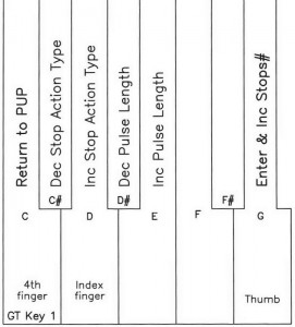
Each StopsX address assignment has to have the type of stop action defined, either SAMs or LEDs. Positional switches that use on/off coils, these are displayed by the name SAMs and momentary switches with some sort of light indication, these are displayed by the name LED’s. When defining SAMs, you are able to enter a pulse length, this being the amount of time that the on/off coils are energized to get this positional switch to change or reverse position.
Enter the Power Up Programming Sequence as instructed in Power Up Programming Overview. ‘Increment’ with key 3 to 4. S/C Switch Hardware and ‘enter’ with key 8. The LCD will display the settings for Stops1.
Use great key 1 to escape or exit. The LCD will auto increment to 5.Define Pistons.
NOTE: When setting the pulse length, you may want to come back to this programming sequence and experiment with the pulse length in conjunction with the voltage setting of the power supply to the magnet coils. Strive for the lowest voltage that is reliable for the quietest operation, balanced with the shortest pulse length for the least amount of duty cycle required by the power supply. This balance will consume the least amount of energy.
Download the full PDF Powerup Programming Document.

