7. Stop Programming – CPx Upgrade
Each stop and swell shoe must be mapped to magnets in the pipe chamber wired to pins on output cards with unique dip switch addresses.
This is done by use of levels, each level being a group of consecutive ascending keys or input pins mapped or programmed to a group of consecutive ascending output pins of the same number, aligned at the low pin of each group.
These levels are calculated from the Input and Output pin lists, and are to be documented on the Programming Levels pin lists before attempting to enter the numbers in this sequence.
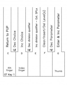
Since this is a spreadsheet implementation where levels are rows, these levels can be manipulated by inserting, deleting, and clearing using key 6 for the choice, key 8 to enter, or key 1 to escape.
Any level that is not used must be cleared using the key 6 choice, and when clear, the word “clear” will be displayed next to the level number.
Enter the Power Up Programming Sequence as instructed in Power Up Programming Overview. ‘Increment’ with key 3 to 7. Stop Programming and ‘enter’ with key 8. The LCD will display “Stop Programming” and “L1”.
The LCD will display the division, or input card address assignment that this stop is to be associated with. Change this division or assignment with key 2 (dec) and key 3 (inc). Qualify key divisions with key 5 for cromatic (cr), diatonic (c), diatonic ( c#), or non-coupling (ncr, nc, nc#) if the key division was assigned ncX in 1. Input Card Address Assignments. Stops1 can be qualified with (cv) for chime volume. AtoD is qualified with the channel number. When correct, enter with key 8.
Use keys 2 and 3 to choose the lkey (low key) or linp (low input) of the input group, and enter with key 8 when correct.
Use keys 2 and 3 to choose the hkey (high key) or hinp (high input) of the input group, and enter with key 8 when correct.
Use keys 2 and 3 to choose the ocaddr or dipswitch address of the output card to which the output group is wired low, and enter with key 8 when correct.
Use keys 2 and 3 to choose the lpin (low pin) of the output group that is to align with the low key or input of the input group, and enter with key 8 when correct. This will finish the level, cancel the selected stop if one was on, and increment to the next level number.
Use great key 1 to escape or exit. The LCD will auto increment to 8. MIDI.
NOTE: Two levels are required for straight chest stops, one level for the stop action (stop not turned on) and one level for the key primaries (stop turned on).
NOTE: Any level that is not used must be cleared using the key 6 choice, and when clear, the word “clear” will be displayed next to the level number.
Click to download the full PDF

