1. Input Card Address Assignments – CPx Upgrade
Each Input Card dipswitch address, from 0 to 15, needs to be assigned a definition as listed in the Wiring Outline-CPU System, IV. Inputs.
Enter the Power Up Programming Sequence as instructed in Power Up Programming Overview.
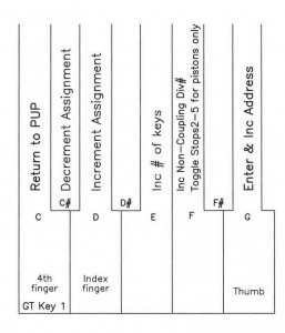
Release keys and/or pistons. 1. Input Card Address Assignments will now be displayed on the LCD.
Any address that exists at the board level but does not have any wiring attached must say ‘Not Used’.
All addresses that do not exist at the board level, hence not in the fiber optic loop, must say ‘Not Used’, except when utilizing a floating division. For this, skip a complete card address, that is base address and base+1 address, these being ‘not used’, then assign the floating division number.
All address assignments can be checked and read from memory by repeatedly depressing the ‘enter’ key 8.
NOTE: When assigning for manual transfers, Div1(GT) and Div4 exchange , or Div5 and Div4 exchange.
NOTE: There are 3 non-coupling divisions, nc1, nc2, and nc3. These can be applied on any keyboard division, in any order. This will allow the non-coupling division qualifiers in 7. Stop Programming.
NOTE: StopsX addresses are more versatile.
Stops1: Stops, Couplers, MIDI stops, Pistons, chime volume.
Stops2&3: Stops, Couplers, MIDI stops, Pistons.
Stops4&5: Stops, Pistons.
NOTE: When Input card addressing assigning, there must be a Stops1. If any Stops2-5 addresses are used for pistons only (this would be the case using optical key contact rails), further assign this address toggling key 6 to say ‘pistons’ meaning that only pistons are wired on this address. Make these ‘piston only’ StopsX assignments the highest of the StopsX numbers, this will limit combination action memory space size to the highest StopsX that is not ‘pistons only’.
Click to download the full PDF

