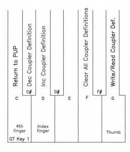
6. Define Couplers
Each Input pin that has been wired to a coupler must be defined. The system scans all of the possible coupler input pins from Stops1 and Stops2 Input card address assignments, as described in the wiring outline. If turned on, the definition choice selected on the LCD will be written into memory or defined for this input pin. Every other pin that is not used for couplers must remain undefined.
Enter the Power Up Programming Sequence as instructed in Power Up Programming Overview. ‘Increment‘ with key 3 to 6. Define Couplers and ‘enter’ with key 8. The LCD will display “Write to Memory” and “D1/D1” “GT/GT 16”.
Use great key 1 to escape or exit. The LCD will auto increment to 7. Stop Programming.
NOTE: Check all stops, pistons, MIDI stops, and swell roller pins that are wired to Stops1 and Stops2 input card address assignments, they must say undefined.
NOTE: If no coupler choice is displayed when entering 6. Define Couplers, this indicates that a possible coupler input pin is on, thus blocking inadvertent programming of the pin.
NOTE: Key 6 will clear or erase or “undefine” all possible coupler input pins.
Click to download the full PDF

