From 1999 to present – 2023
This CPU system, an evolution of the Copper Box System, takes advantage of the ever increasing capabilities of the microprocessor, memory, and related components to enhance and enlarge all capacities of pipe organ control. Expanding the use of fiber optics to communicate between all circuit boards has eliminated the many plug connection points of the backplane/mother/daughter board layout. Only three types of circuit cards, Input, Output, and CPU combine to make a complete integrated control system for any pipe organ, and ‘in system programming’ makes these generic cards into a unique installation. This programming is done by the organ builder after wiring, using the already existing low 8 keys of the Great division keyboard. A partial list of maximum numbers for this CPU system are 9 keying divisions including pedalboard, 26 general pistons, 72 divisional pistons, 256 total stops and couplers, 7 swell pedals, and 512 rank outputs. All of the features of the Copper Box system have been retained, enhanced, and increased, both in raw numbers and ease of use.
The first circuit board is the CPU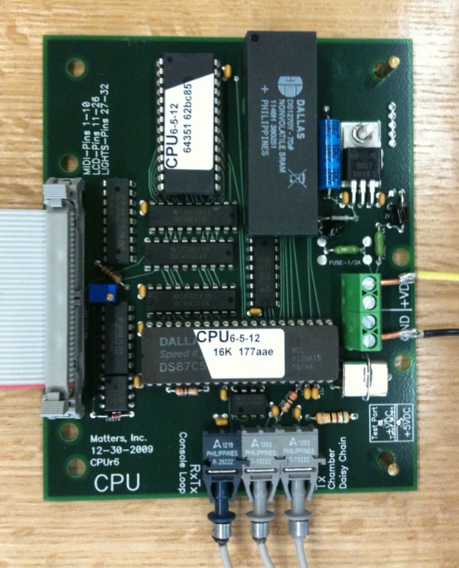 board or central processing unit, only one is required per pipe organ installation. This controls and stores all aspects of the pipe organ, from coupling to combination action, and record/playback to name a few. It is located in the console where it reads all console inputs, writes to combination action magnet outputs, writes note on/off data to the pipe chambers, writes to the LCD for system status, interfaces directly to MIDI
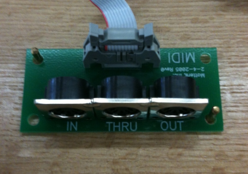 , and contains non-volatile memory for record/playback.
The second is the Input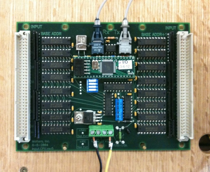 board which reads all inputs from the console: keyboards, stops, couplers, pistons, and expression pedals. Each board has two unique addresses of 64 pins each, for a total of 128 inputs. These 64 pin address logically allow for 61 note key divisions or other combinations of inputs depending on certain definitions. Each Input board has a microprocessor and a fiber optic receive/transmit link to talk with the CPU board.
The third is the Output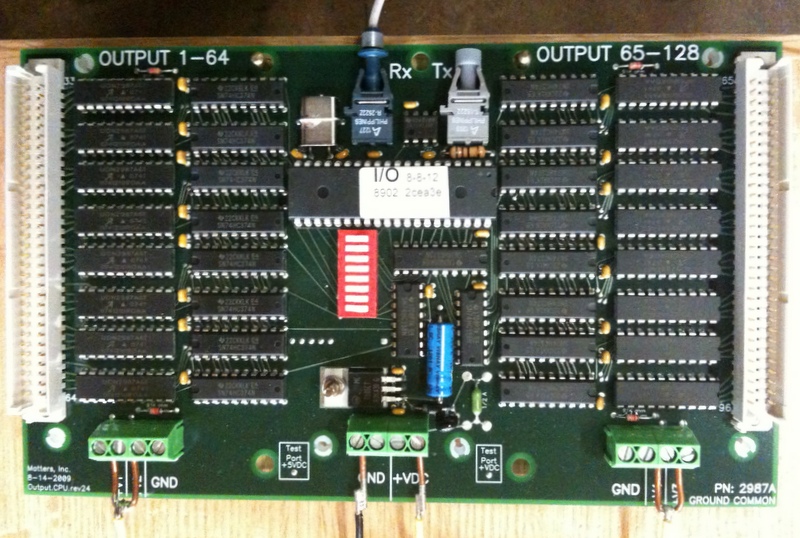 board, interfacing between the CPU and all magnet coils, either in the console for the combination action or in the pipe chambers for windchest and swell shade control. Again, each output card has a microprocessor, a fiber optic receive/transmit to communicate with the CPU board, unique address, and 128 outputs arranged in two groups of 64.
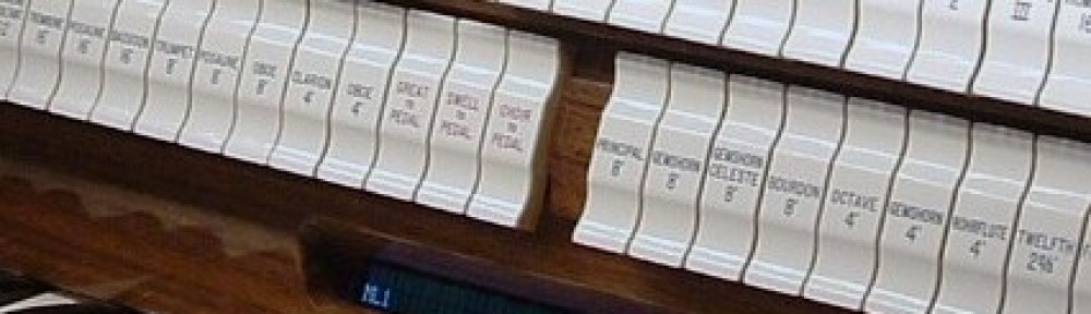
An LCD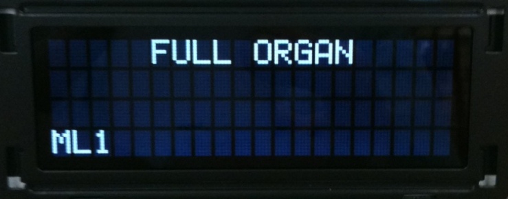 reports system status for the organist. The organ builder uses this LCD to program the generic Input and Output circuit boards into a unique instrument, and to troubleshoot by monitoring system status.
All of the circuit cards in the console are connected via a single fiber optic loop, thus communicating all data or inputs to the CPU and transmitting all outputs for combination actuation from the CPU. The chamber is connected via a single fiber to receive all note on/off communication from the CPU card.
A fiber optic repeater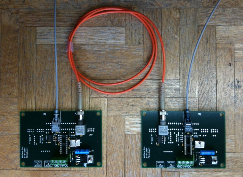 or conversion board is needed when distances between console and chamber exceed cable lengths of 100’. Plastic fiber optic cable is used when distance is less than 100’ else glass fiber optic cable is required. To use glass cable, the plastic fiber needs to be converted to glass fiber requiring one of these boards at each end to convert to/from plastic/glass. Also this board can be used as an intermediate repeater to extend the transmission length of plastic cable by retransmitting the data at full strength to offset the light loss inherent in distances over 100′.
Added in 2003 is the optional AtoD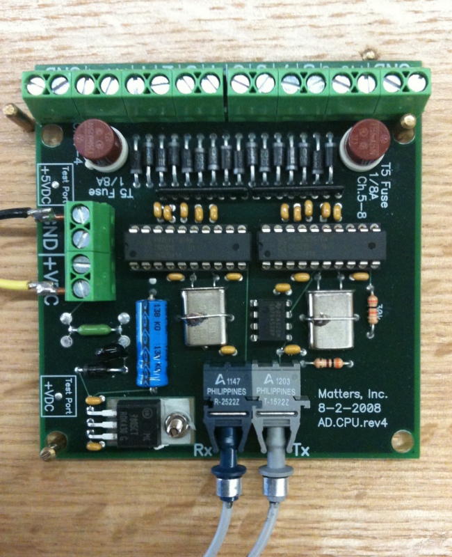 or Analog to Digital conversion of the expression pedals through the use of slide or rotary potentiometers to read pedal positions. This single card, which can read up to 8 pedals, is powered by a microprocessor and a fiber optic receive/transmit to communicate with the CPU board.
The LED/photo transistor key contact rail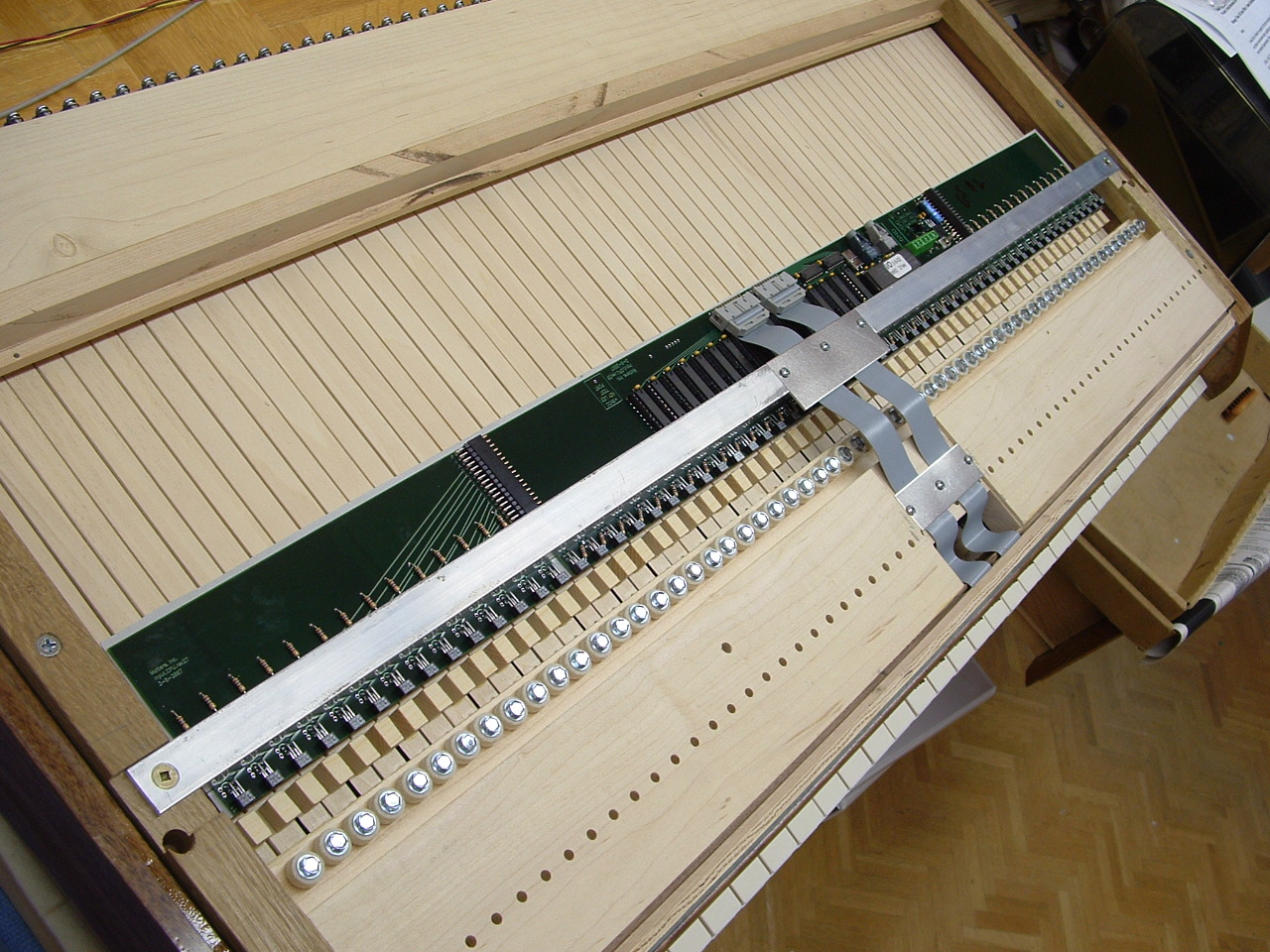 , added in 2007 as an optional way to wire a keyboard, is an application of the existing Input card to read a keyboard without using mechanical contacts, thus no moving parts to wear out. Functionality is exactly as the existing Input card, the base address reading the keyboard and the base address+1 able to read piston inputs. This eliminates any individual contact wiring and cabling, linked only by power and fiber optics to the CPU card.
The CPx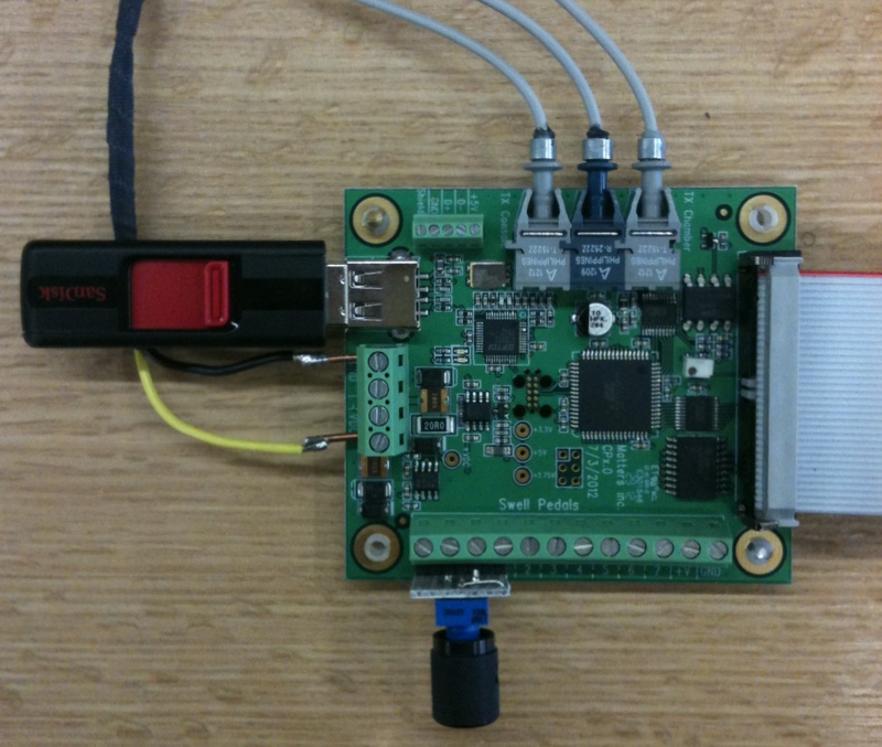 upgrade or replacement for the CPU board occurred in 2012. This surface mount technology board incorporates a USB port for thumb drive or flash drive memory storage of all memory levels and record/playback functionality. Also embedded in this board is the AtoD capability requiring the use of potentiometers to read the expression pedal positions. This upgrade board is fully backward compatible with the CPU/Input/Output layout.
An upgraded Output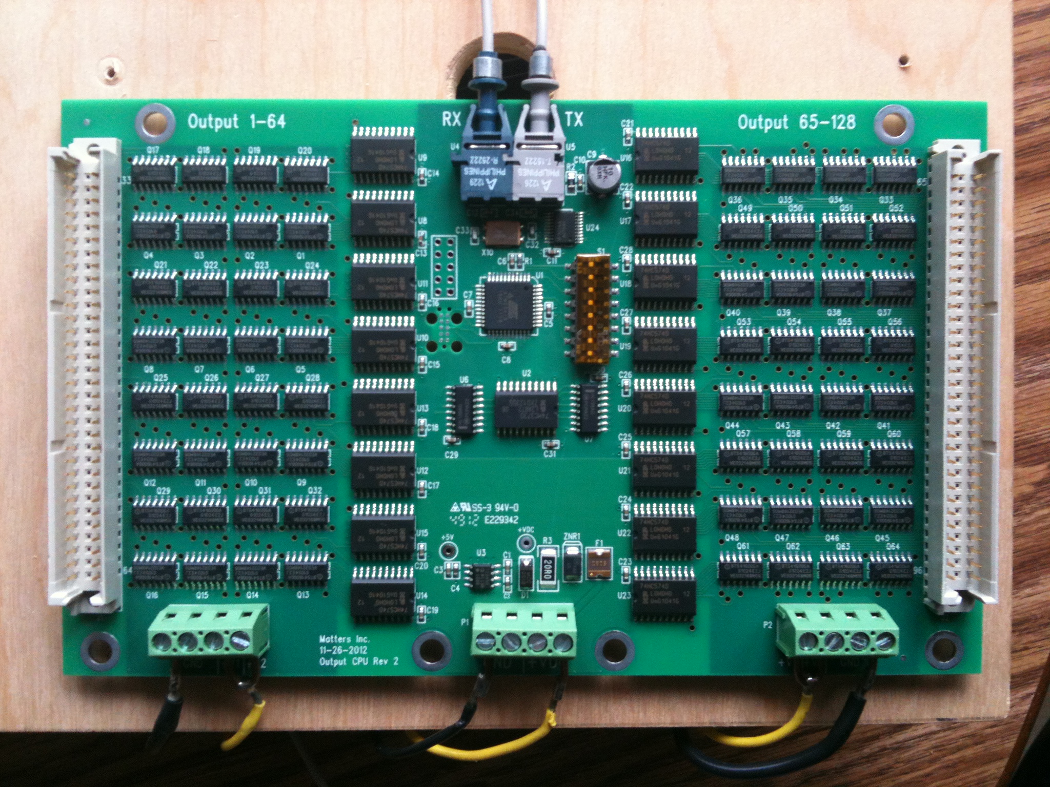 board, available in 2013, incorporates the use of surface mount chips and new high current driver chips. These chips, available in either polarity, negative common – high side switching, or positive common – low side switching, can now handle 1.2 amps per pin with no heat rise. Advantages of these new switches are protection against thermal, overload, over current, over voltage, and ESD. The result is a chip that will not be damaged if a magnet coil or output wire is shorted out. Combination action magnets, pull-down magnets, and low resistance pedal action magnets can be controlled with no additional or external components at 100% duty cycle.
While individual optical pedal key contacts were available since 2010, 2014 saw the introduction of a 4 circuit card layout that put 32 sensors in place for reading the pedalboard without any wiring harness. Thin enough to bend to match the curve at the front of a pedalboard, this set is designed to be mounted in the bottom of the console and “read” the end of the wood pedal key as if moves down in front of the sensor.
In 2014 a surface mount version of the Input 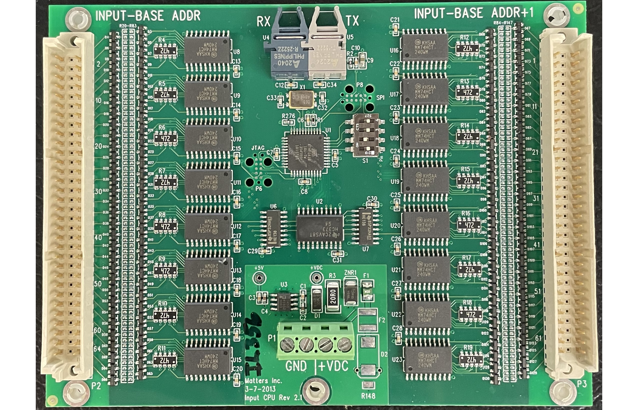 card was introduced, completely compatible both in size, layout, and functionality as the through hole board that it replaces.
Also upgraded to surface mount technology was the fiber optic repeater and translator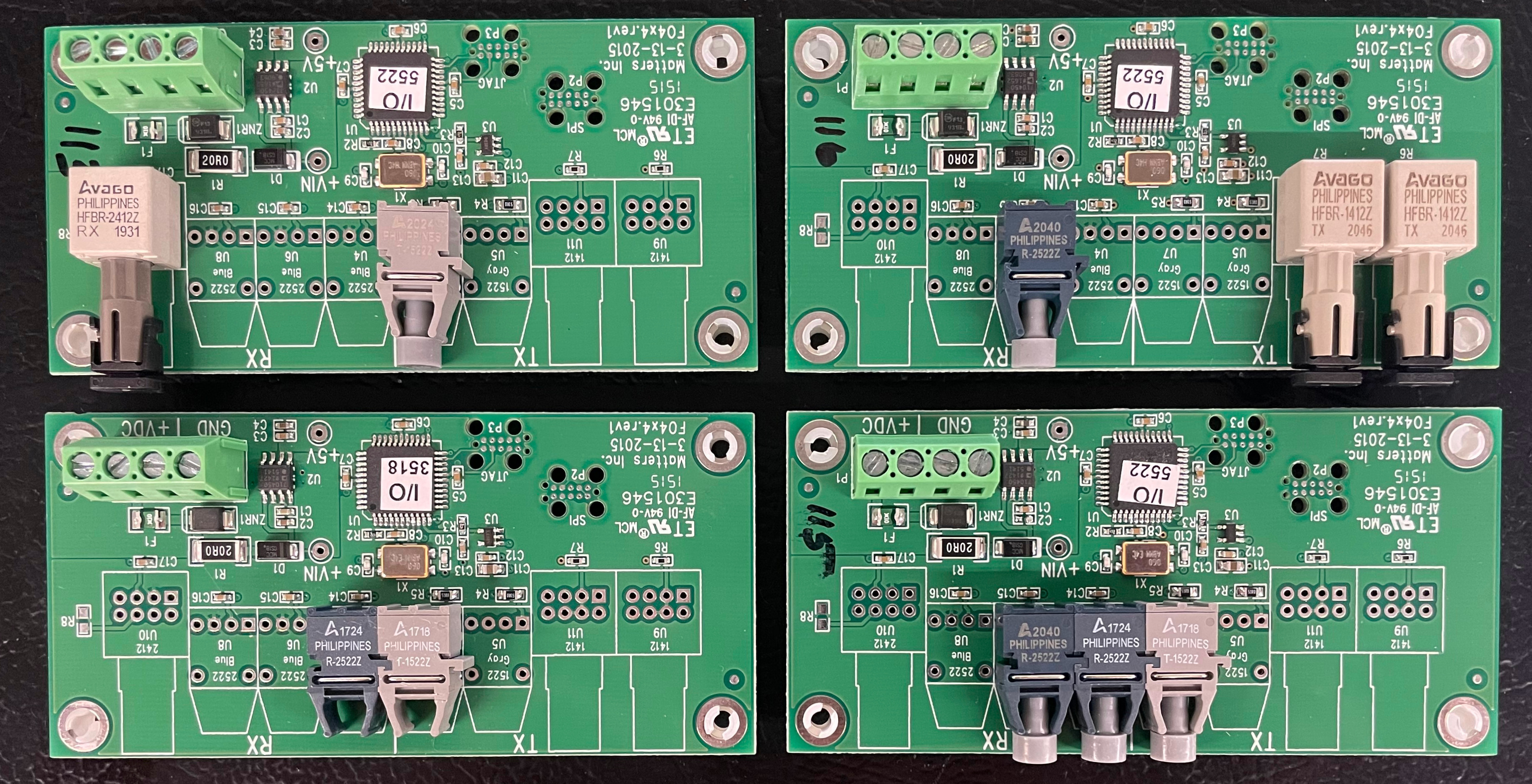 board. This board can now re-transmit or convert plastic fiber cable to glass and the reverse converting glass fiber to plastic. Multiple ports are available to allow for direct communication to multiple chambers or multiple console locations.
2015 saw the introduction of printed circuit card piston slips that utilized either a low profile square button short throw toggle switch or the use of long throw round switches from organ supply houses. This circuit board mounting of pistons removes the most tedious wiring in a pipe organ, allow pistons to connect to the optical keyboard contact card via a single ribbon cable. With the removal of 2 wires, + and – and unsnapping the fiber optic pair, the keyboard with piston slip and contact rail can be moved to the bench as a single and complete unit.
2016 saw a rework of the surface mount Output card smt- 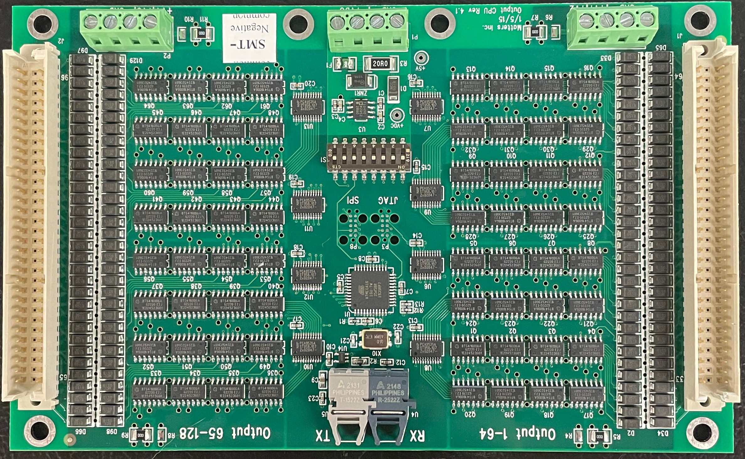 introduced in 2013 using I/O expanders. This allowed the replacement of 19 integrated circuit chips with 8, the goal of ever reducing component counts.
At the end of 2019, a new version of the CPx card was introduced. While not visually different from the 2012 version, the microprocessor chip set is upgraded in memory size and clock speeds. But more importantly, this card is running a completely new object oriented language OS designed to bridge the gap til wireless takes over the control of pipe organs in the next generation. While compatible with all previous hardware components, the intent of this board is to replace the CPU cards of all previous systems, thus making all systems “new”. Many updates in “power up programming” make it simpler and easier to setup.
2020 saw continued development of the CPx OS. Of particular note, the memory levels use a compressed format to reduce bandwidth when reading and writing, a typical reduction is 80%. Also a conversion utility is available that converts the “power up programming” file into spreadsheet format for viewing and printing.
In 2021, the development was completed of the “tuning app” for iphones: a user interface to play, test, and tune pipes while mobile in the pipe chamber.  This incorporates a small circuit card
 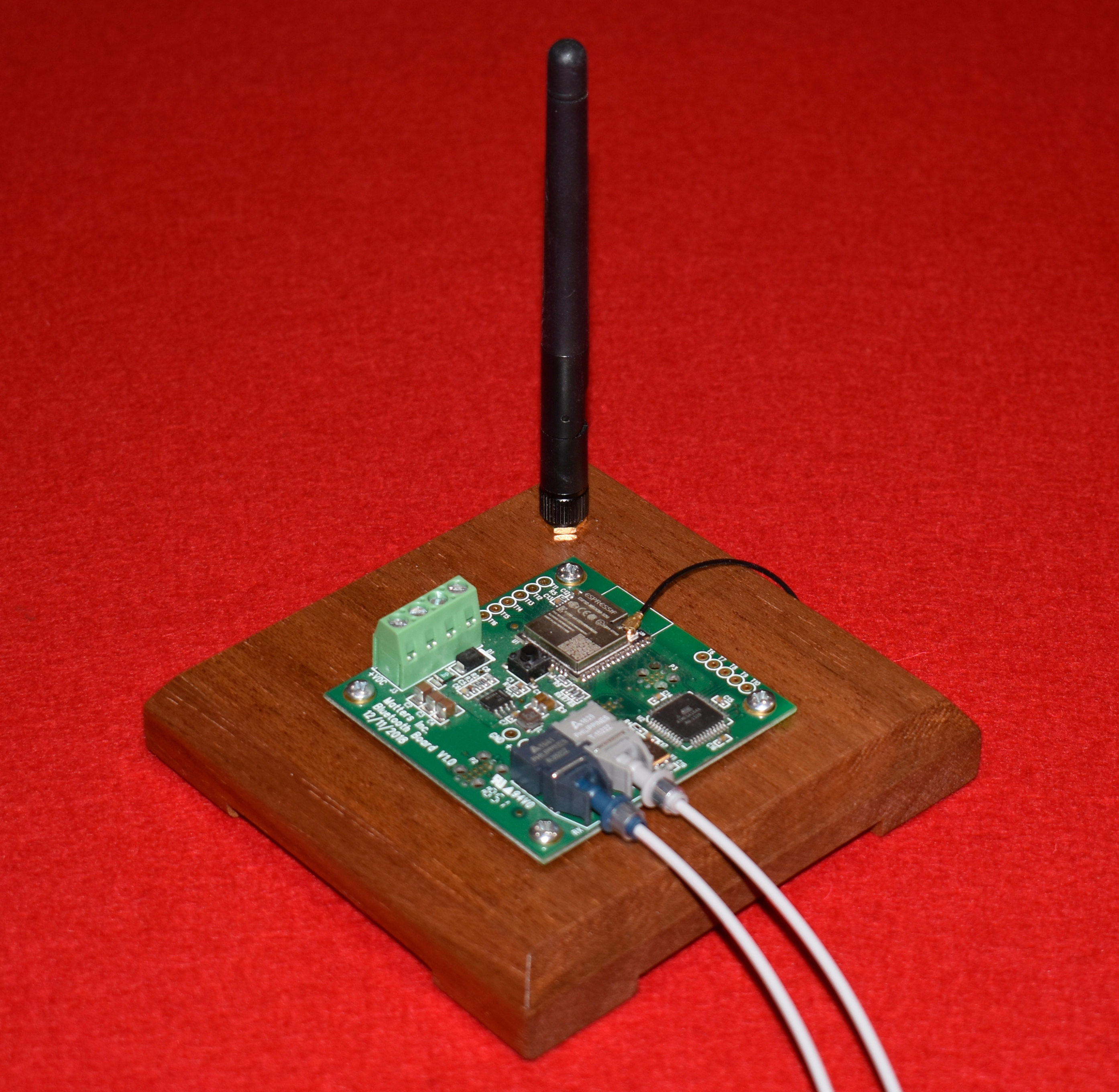 with antennae and operates via bluetooth https://en.wikipedia.org/wiki/Bluetooth interface.
2022 saw the completion of a new chamber output panel. This panel comes completely wired from power supply leads incorporating all proper wire and fuse sizes. Chest cables are now punched down using the “110” standard The Output card is now a simple plug in whereby exchange can be made without removing a single wire! Also LEDs are present for diagnostics of each output, power, and communication! As well the fuse blocks have obvious LEDs indication of a blown fuse! With so many improvements, it almost make one want to go back to previous generations and rewire!.
2022 also saw the completion of development and testing of new SAMs control in the console whereby the Input sense and Output On/Off circuitry is combined to eliminate wiring and keep the flyback diodes right at the coil! Again, with so many improvements, it almost make one want to go back to previous generations and rewire!
More to come in 2023!!!!!