12. A to D – CPU
Analog to Digital is the interface whereby a potentiometer is used to measure an expression pedal position (analog) so that this variable voltage reading can be converted to a number (digital) for communication to the CPU card. Each pedal is hooked to its own potentiometer, thus making for a unique channel number. This channel number has to be defined by use, low number (closed position), high number (open position), and number of contacts that are going to be mimicked if this was the old style discreet contact roller. When defined as the crescendo, each ‘virtual’ contact is treated as a general piston.
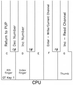
Enter the Power Up Programming Sequence as instructed in Power Up Programming Overview. ‘Increment’ with key 3 to 12. A to D and ‘enter’ with key 8. The LCD will display “AtoD” and “enabled” or “disabled”.
Move pedal to open or maximum position and enter with key 6. The blinking block will move over to the # of contacts.
Use key 3 to select the number of contacts to mimic and enter with key 6. The blinking block will disappear and the channel number will increment and display the settings for this next channel .
Key 1 will exit or escape and the LCD will return with 1. Input Card Address Assignments.
Download the full PDF Powerup Programming Document.

