From 1999 to 2012
This CPU system, an evolution of the Copper Box System, takes advantage of the ever increasing capabilities of the microprocessor, memory, and related components to enhance and enlarge all capacities of pipe organ control. Expanding the use of fiber optics to communicate between all circuit boards has eliminated the copper box enclosers along with their many connectors required by the backplane/mother/daughter board layout. The use of only three types of circuit cards was retained: Input, Output, and CPU. Also expanded was the ‘in system programming’, making these generic cards into a unique installation, now done by the low 8 keys of the GT keyboard. Maximum numbers for this CPU system are 9 keying divisions including pedalboard, 128 pistons, 256 total stops and couplers, 7 swell pedals, and 512 rank outputs. All of the features of the Copper Box system have been retained, enhanced, and increased, both in raw numbers and ease of use.
Example console application:

Example chamber installation:

The first circuit board is the CPU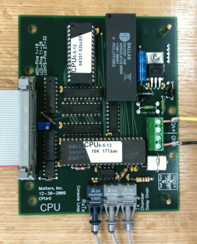 board or central processing unit, only one is required per pipe organ installation. This controls and stores all aspects of the pipe organ from coupling to combination action and record/playback to name but a few. It is located in the console where it reads all console inputs, writes to combination action magnet outputs, writes note on/off data to the pipe chambers, writes to the LCD for system status, interfaces directly to MIDI, and contains non-volatile memory for record/playback.
The second is the Input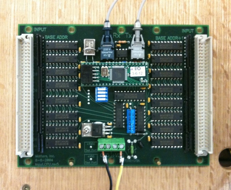 board which reads all inputs from the console: keyboards, stops, couplers, pistons, and expression pedals. Each board has two unique addresses of 64 pins each, for a total of 128 inputs. These 64 pin address logically allow for 61 note key divisions or other combinations of inputs depending on certain definitions. Each Input board has a microprocessor and a fiber optic receive/transmit link to talk with the CPU board.
The third is the Output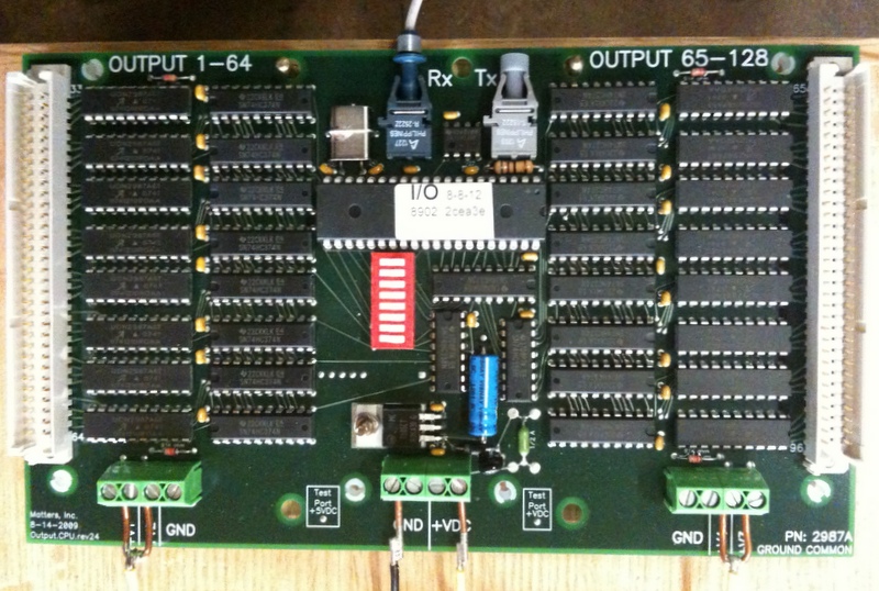 board, interfacing between the CPU and all magnet coils, either in the console for the combination action or in the pipe chambers for windchest and swell shade control. Again, each output card has a microprocessor, a fiber optic receive/transmit to communicate with the CPU board, unique address, and 128 outputs arranged in two groups of 64.
An LCD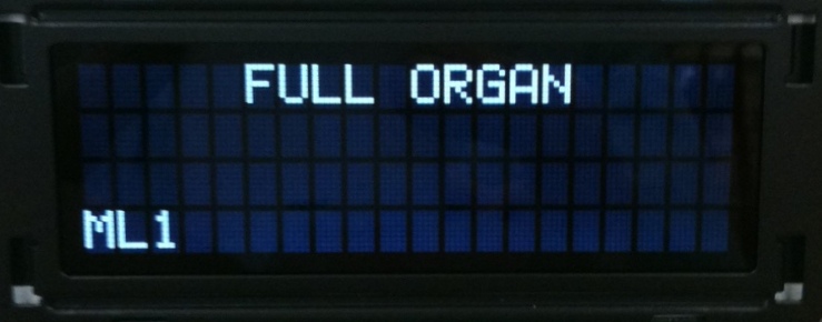 reports system status for the organist. The organ builder uses this LCD to program the generic Input and Output circuit boards into a unique instrument, and to troubleshoot by monitoring system status.
All of the circuit cards in the console are connected via a single fiber optic loop, thus communicating all data or inputs to the CPU and transmitting all outputs for combination actuation from the CPU. The chamber is connected via a single fiber to receive all note on/off communication from the CPU card.
Use of a fiber optic repeater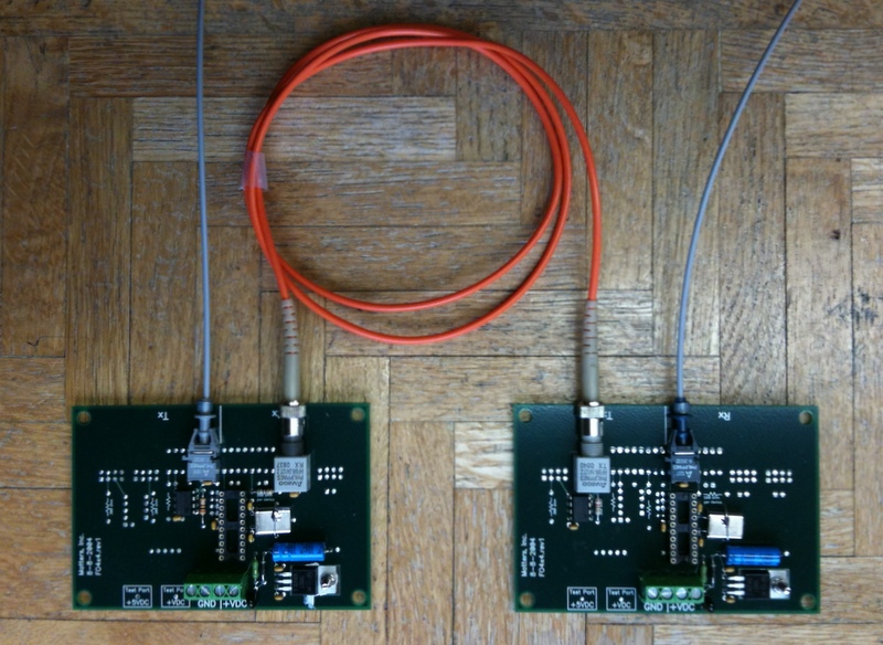 or conversion board is still needed when distances between console and chamber exceed cable lengths of 100’. The use of repeaters also allows for a remote console whereby the second console is linked to the first by adding more input and output cards in the fiber loop.
Added in 2003 is the optional AtoD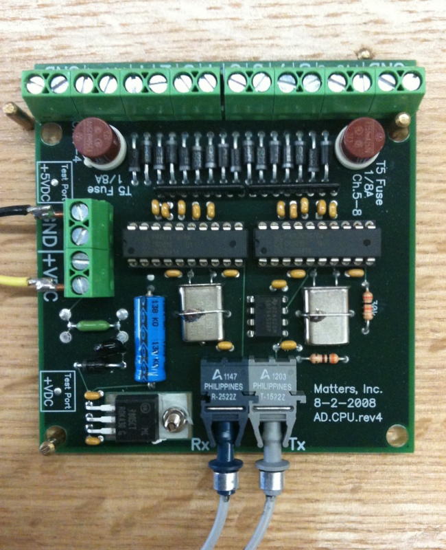 or Analog to Digital conversion of the expression pedals through the use of slide or rotary potentiometers to read pedal positions. This single card, which can read up to 8 pedals, is powered by a microprocessor and a fiber optic receive/transmit to communicate with the CPU board in the console loop.

The LED/photo transistor key contact rail
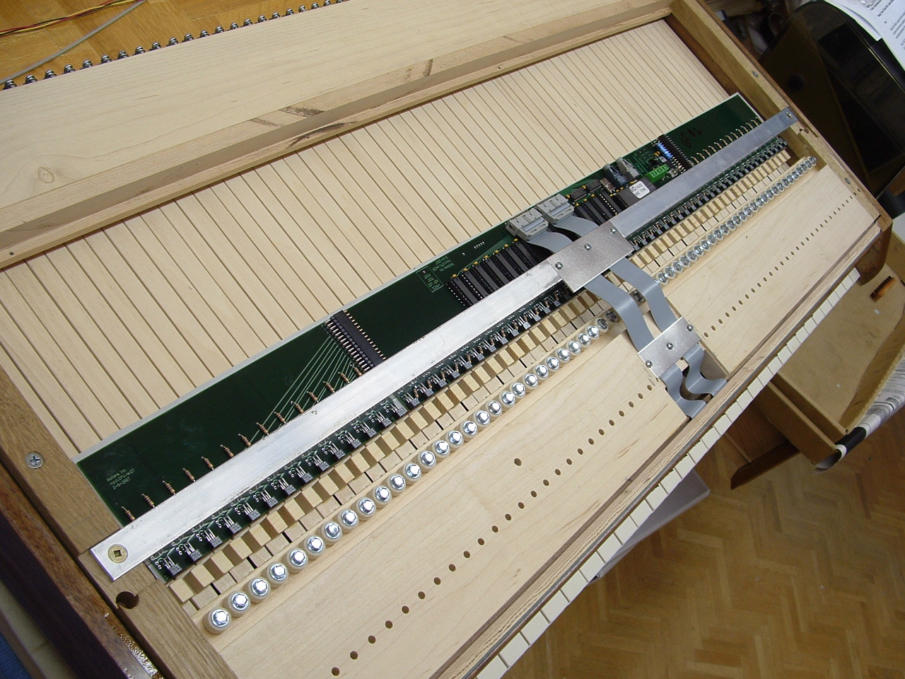
added in 2007 as an optional way to wire a keyboard, is an application of the existing Input card to read a keyboard without using mechanical contacts, thus no moving parts to wear out. Functionality is exactly as the existing Input card, the base address reading the keyboard and the base address+1 able to read piston inputs. This eliminates any individual contact wiring and cabling, linked only by power and fiber optics to the CPU card.
Documentation and user manuals are found under this CPU tab, please use them.